We use cookies to make your experience better. To comply with the new e-Privacy directive, we need to ask for your consent to set the cookies. Learn more.
K&N Engineering Air Filtration Efficiency Testing Protocol

Scope and Application
K&N Filters performs air filter tests for efficiency and capacity in compliance with the ISO-5011 Standard for Performance Testing of Inlet Air cleaning equipment for internal combustion engines and compressors. Previous to the adoption of the ISO-5011, testing was performed in compliance with the SAE J-726 - Air Cleaner Test Code. The ISO standard states that the basic performance characteristics of greatest interest are air flow restriction, dust collection efficiency, and dust capacity. K&N adheres to the ISO standard in the measurement of these test parameters.
Lab Environmental Conditions
K&N maintains the ISO Filtration Lab at 70° F and 50% RH within the limits of the ISO standard for normal testing.
Calibration and Equipment Checks
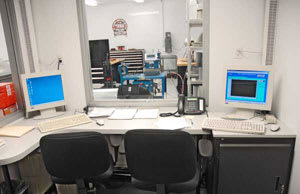
Check Lab conditions each morning to verify they are stable and within the prescribed limits. Verify that the dampers are open and operate the system air blowers at a predetermined rate. Monitor computer data channels to ensure that all instruments are working properly. Verify that the digital cameras are charged and operational.

Allow test dust to acclimate to lab conditions for 24 hours and load the necessary amount into the dust feeder hoppers for the first test to be performed.
Set the weighing oven to 105°C (221°F) and allow it to come up to operating temperature.
Periodically - Validate the efficiency of absolute filter media as required by the ISO standard. Calibrate instrumentation periodically as required by the calibration schedule.
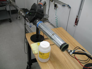
Test Fixtures
K&N uses three types of fixtures to enable testing of the broad types, shapes and sizes of the filter we manufacture. For OEM replacement filters we have found that using the OEM air box or filter housing allow the best comparison and repeatability when testing these filters. Another type of fixture used is a filter housing conforming to the design specifications spelled out in the ISO 5011 protocol. This ISO Fixture is used for specific testing as specified by the engineering staff as well as for most round filters. Lastly, K&N has developed a cabinet type of fixture, modeled after the ISO fixture for testing universal clamp-on type filters. This cabinet allows repeatable consistent dust loading of these open element type filters.
Once the test fixture has been specified, the Dust Test procedures are the same for all filter types except for some minor differences in mounting, orientation and placement of the dust nozzle and pressure taps which become apparent when finalizing the setup of the test apparatus.

Lab Test Procedures
Condition and Restriction Test - Verify that the dust feeder has been loaded with the proper amount and type of dust for the test to be performed.
Install a new absolute filter into the test stand filter tray. Condition the absolute filter at 110% of the rated flow of ambient air for 15 minutes to reduce any subsequent errors in measurements caused by losses of fibers or materials. The conditioning of the absolute filter can be performed in the Manual Test Mode.
While performing absolute filter conditioning, prepare test data sheets and other required documentation, mark test articles with appropriate task number, photograph test articles and create test folder on the appropriate server as required. Record the test information into the control computer and create the necessary data file in the appropriate folder.
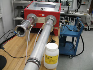
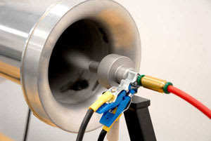
Install the test article (fixture) onto the test stand specified in the test request. The connections for the upstream and downstream pressure measurements are made using the two tubes marked Test Filter Restriction and Test Filter Delta-P. The tubes are connected depending on the fixture to be used as follows:
ISO Housing or Dust Cabinet - Install the tube marked Test Filter Restriction to the dust cabinet outlet tube pressure port (clean side of the filter). Install the tube marked Test Filter Delta-P to the dust feed tube pressure port (dirty side of the filter). Attach grounding cables to test fixture and test article as recommended by the ISO test standard.
OEM Air box - Install the tube marked Test Filter Restriction to the upstream absolute filter pressure port of the test stand plenum. Leave the tube marked Test Filter Delta-P open to atmosphere. Attach grounding cables to test stand and test article as recommended by the ISO test standard.
Perform the Condition and Restriction Test using test filter and absolute filter at the air flow rate specified by the test request. Condition the test apparatus for 15 minutes as required by the ISO standard. Measure and record the restriction and differential pressure versus flow rate at 50%, 75%, 100%, 125%, and 150% of the requested air flow rate.
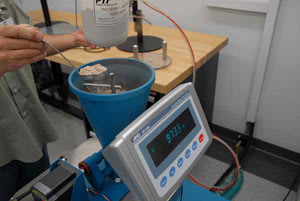
Measure and record the mass of the test article and dust chamber (fixture). Stabilize an absolute filter using the ventilated oven at the required temperature. Measure and record the mass of the absolute filter.
Reinstall the absolute filter and test article with fixture into the appropriate test stand. Re-attach grounding cables to test fixture and test article as recommended by the ISO test standard.

Initial Efficiency Test
The purpose of the Initial Efficiency Test is to determine the dust retention capability of the test article when loaded with an initial amount of test dust.
The initial efficiency will be determined after the addition of 20g of dust or the number of grams numerically equivalent to 6 times the air flow in m3/min (cubic meters / minute), whichever is greater. Using the appropriate worksheet, determine the actual number of grams to be applied in the initial efficiency test based on requested flow rates and enter the appropriate amounts including the termination criteria into the control computer. Enable the control computer to record all necessary data parameters for the duration of the test.
At the Lab computer interface, lock in the scale reading by checking the appropriate dialog box. Switch on the blower and verify that it reaches the required test air flow rate and allow the system to stabilize. Turn on the dust feeder using the dialog box control button and record the initial restriction (delta-p).
Monitor the system parameters until the termination point has been reached. The control computer will automatically shut down the blower and dust feeder at the termination point. Record screen data on the appropriate data sheet and file it in the test folder.
Remove the test filter, fixtures and the absolute filter from the test stand. Photograph the test article and fixtures, and note any anomalies in the comments section of the datasheet. Place the absolute filter in the ventilated oven and periodically check for the weight to stabilize. Record the final absolute filter weight on the data sheet.
Weigh the test filter and fixture. Record the weight(s) on the appropriate data sheet. If the test filter reached its full-life termination pressure during the initial test phase, record that fact in the data sheet and archive the test filter, otherwise prepare the test filter and fixtures for the full-life/capacity test.
Full-Life/Capacity Test
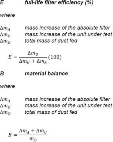
The purpose of the Full-Life/Capacity Test is to determine the total mass of dust retained by the test filter by recording the incremental weight of the dust fed until the test filter reaches a terminating pressure restriction as specified by the test request.

The full-life efficiency will be determined after adding a quantity of dust at the rate of 1 g/m3 (grams per cubic meter) until the test filter reaches a predetermined pressure restriction. Enter the air flow rate, dust feed rate, and termination pressure into the control computer dialog box. Set the control computer to record all necessary data parameters for the duration of the test.
Reinstall the absolute filter, test filter and appropriate fixture onto the test stand. At the Lab computer interface, lock in the scale reading by checking the appropriate dialog box. Switch on the blower and verify that it reaches the required test air flow rate and allow the system to stabilize. Turn on the dust feeder using the dialog box control button and record the initial restriction (delta-p).
Monitor the system parameters until the termination point has been reached. The control computer will automatically shut down the blower and dust feeder at the termination point. Record screen data on the appropriate data sheet and file it in the test folder.
Remove the test filter, fixtures and the absolute filter from the test stand. Photograph the test article and fixtures, and note any anomalies in the comments section of the datasheet. Place the absolute filter in the ventilated oven and periodically check for the weight to stabilize. Record the final absolute filter weight on the data sheet.
Weigh the test filter and fixture. Record the weight(s) on the appropriate data sheet and archive the test filter.
Appendix A: Equations and Formulas